A Comprehensive Analysis of Ferrule Crimping Technology
Core Process Principles and Scope of Application
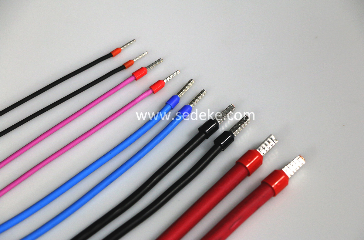
The core logic of ferrule crimping is the "Cold Weld" effect. High-intensity pressure induces plastic deformation in the terminal’s metal sleeve, binding multi-stranded flexible wires into a compact, confined space.
- Physical Essence: The crimping force expels air from between the wire strands, allowing the contact surfaces to achieve atomic-level proximity, which effectively prevents oxidation.
- Applicable Scenarios: Primarily used for stranded wires.
- Key Advantages: It solves the common issues encountered when inserting flexible wires directly into screw terminals, such as wire breakage, high contact resistance, and loosening caused by thermal cycling.
Pre-Crimping Preparation: Materials, Tools, and Pre-processing
| Process Segment |
Key Requirements |
| Material Matching |
Must follow the 1:1:1 Rule: Wire Gauge = Terminal Specification = Die Specification. |
| Equipment Selection |
Prioritize the use of Quadrilateral (4-point) or Hexagonal (6-point) crimping tools. |
| Wire Inspection |
Verify that conductors are free of oxidation (blackening) and broken strands, and that the insulation layer has no cracks. |
Standard Crimping Workflow (Automation Upgrade)
In the manual era, stripping and crimping were separate tasks. In an automated workflow, these two steps are highly integrated to prevent strand splaying and oxidation.
Example Case:
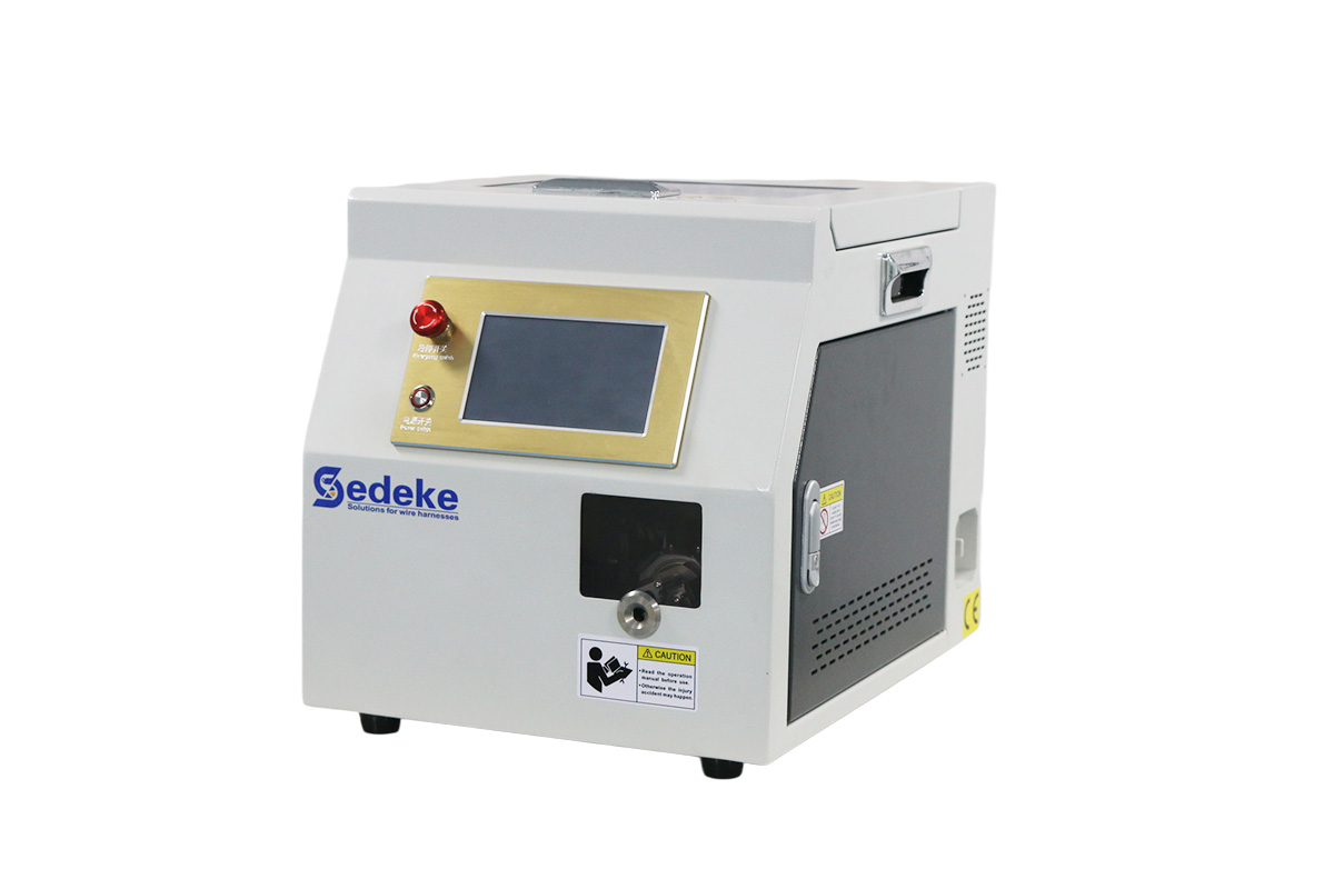
TM-E140 Pre-insulation Ferrule Terminal Strip And Crimp Machine
1.Parameter Setting & Pre-check
Equipment Initialization
Adjust the stripping depth and crimping stroke of the TM-E140 based on the wire gauge. Ensure the ferrule specifications (e.g., E1508) in the vibratory bowl feeder perfectly match the current wire being processed.
2.Wire Feeding
Sensor Trigger
Feed the wire horizontally into the machine’s inlet. Automated machines are typically equipped with sensors that automatically trigger the stripping action once the wire reaches the preset position.
3.Precision Stripping
Zero-damage Core Protection
The machine utilizes V-shaped stripping blades to precisely cut the insulation. Unlike manual stripping, the integrated stripping-crimping machine ensures a constant strip length and prevents secondary twisting or splaying because the crimp happens instantaneously.
4.Instant Twisting
Preparation for Insertion
Immediately after stripping, the machine automatically performs a wire twisting motion. This keeps the strands tight and aligned, preparing them for smooth insertion into the ferrule.
5.Ferrule Positioning & Insertion
Automated Feeding
The vibratory bowl feeder aligns and pushes the terminals to the crimping station. The internal mechanism then guides the stripped wire core precisely into the bell-mouth of the ferrule.
6.High-Precision Crimping
Inverter Motor Driven
The TM-E140 employs inverter control, providing a more stable pressure curve than pneumatic or manual tools. This ensures perfect plastic deformation of the metal sleeve, achieving the "Cold Weld" effect.
7.Quality Inspection
Real-time Monitoring
Examine the finished product. Check for a slight protrusion of the wire core (0–0.5 mm) from the front of the ferrule and ensure the wire insulation is perfectly encased by the terminal's collar.
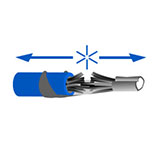
8.Pull-out Force Sampling
Physical Verification
Periodically take samples from the production line for tensile testing (per IEC 60352-2 standard) to ensure the machine maintains stable pressure output during long-term operation.
Quality Enhancement through Automation
By implementing automated crimping machines, you can achieve technical improvements across the following three dimensions:
- Pressure Consistency: The inverter-driven motor eliminates the inconsistent force typically caused by operator fatigue in manual crimping processes.
- Space Efficiency: The cross-section after automated crimping is extremely dense (void rate < 5%), ensuring smoother insertion of terminals into compact PLC modules.
- Material Savings: An exceptionally high success rate reduces the waste of terminals and expensive cables caused by crimping defects.
Quality Acceptance Standards (National & International Standards)
4.1 Core Standards & References
National Standards (GB): GB/T 14315-2008 (Crimping terminals for power cables); GB/T 18290.2-2015 (Equivalent to IEC 60352-2).
International Standards: IEC 60352-2:2024 (Solderless connections - General requirements); UL 486A/B (Standard for Safety for Wire Connectors).
4.2 Acceptance Indicators
| Dimension |
Acceptance Criteria |
Inspection Tools |
| Appearance |
No cracks, bulges, or burrs in the crimping zone; no exposed core strands; no damage to the insulation layer. |
Visual Inspection + Caliper |
| Mechanical Performance |
Tensile Test: $\ge 50N$ for $1.5mm^2$ wire; zero relative displacement between terminal and conductor. |
Pull Force Tester |
| Electrical Performance |
Contact Resistance: $\le 1.1\times$ the resistance of an equivalent length of wire; Insulation Resistance: $\ge 1M\Omega$ (tested at 500V). |
Micro-ohmmeter, Megohmmeter |
| Dimensional Accuracy |
Outer diameter deviation after crimping $\le \pm5\%$; indentation depth must conform to die specifications. |
Digital Caliper |
Common Issues and Solutions
| Issue Type |
Typical Manifestation |
Root Cause |
Solution |
| Loose Connection |
Overheating after power-on; resistance exceeds standards. |
Wire core not fully inserted; crimping height is too high. |
Recalibrate stripping length; adjust crimp parameters; re-crimp and re-test resistance. |
| Core Breakage |
Wire breaks during tensile test; terminal falls off. |
Over-crimping; insufficient stripping length. |
Adjust crimping height to 70%–80% of original diameter; standardize stripping to avoid core damage. |
| Crimping Cracks |
Visible cracks on terminal; open circuit after power-on. |
Incorrect parameter settings; crimping speed is too fast. |
Readjust parameters; ensure steady and uniform pressure application. |
| Poor Contact |
Signal fluctuation; intermittent power loss. |
Conductor oxidation; lack of conductive paste. |
Clean oxidation layer from core; apply electrical joint compound; re-crimp. |
| Insulation Damage |
Leakage; risk of short circuit. |
Stripping length too long; insulation damaged during crimping. |
Precisely control stripping length; use appropriate stripping machines; avoid excessive force. |
Operational Precautions & Safety Standards
- Equipment Maintenance: Periodically calibrate the crimping machine. Inspect and clean worn components to prevent mechanical wear from compromising crimping quality.
- Environmental Requirements: Operate in a dry, dust-free environment. Avoid high-humidity or corrosive atmospheres to prevent terminal oxidation.
- Safety Protocols: Perform operations only after power-off verification. Wear insulated gloves and strictly prohibit touching energized terminals with bare hands.
- Batch Quality Control: Conduct random sampling (10%) for each batch. If any defect is found, perform a 100% inspection to ensure consistent process quality.
Summary
High-quality ferrule crimping is the cornerstone of industrial electrical automation. The essence of mastering this technology lies in the professionalization of tools and the standardization of workflows. By strictly implementing the "Seven-Step Method" and standardized acceptance procedures, over 95% of potential electrical connection hazards can be eliminated.

 EC-6100 Automatic Heat Shrink Tube Cutting Machine EC-6800 Automatic Cutting Machine EC-6100H Automatic Hot Cutting Machine EC-830 Corrugated Tube Cutting Machine EC-6500 Automatic Cable and Tube Cutting Machine EC-810 Automatic Cable Cutting Machine EC-850X Automatic Rotary Cutting Machine EC-821 Corrugated Tube Cutting Machine EC-890 Multifunctional Automatic Cutting Machine EC-870 High-power Automatic Tube Cutting Machine EC-816 Automatic Cutting Machine EC-823 High Speed Cutting Machine EC-805 Automatic Cable Cutting Machine EC-860 Corrugated Tube Cutting Machine EC-830F Automatic Tube Cutting Machine With Feeding System EC-830FS Tube Cutting Machine With Feeding System EC-3100 Automatic Cable and Tube Cutting Machine
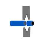 CS-4507/6010 Multifunctional Wire Stripping Machine UniStrip 2016 Pneumatic Wire Stripping Machine UniStrip 2018E Electric Cable Wire Stripping Machine CS-5507 Automatic Coaxial Cable Stripping Machine CS-5515 Automatic coaxial cable stripping machine CS-400 Braided Shield Cable Stripping Machine CS Series Rotary Cable Stripping Machine CS-2486 Coaxial Cable Wire Stripping Machine
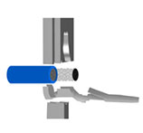 TM-20 Terminal Crimping Machine TM-20S Automatic Wire Terminal Crimping Machine TM-200 Terminal Crimping Machine TM-10P Registered Jack Crimping Machine TM-E140 Pre-insulation Ferrule Terminal Strip And Crimp Machine TM-E140S Automatic Wire Stripping Ferrule Crimping Machine TM-P300 Pneumatic Terminal Crimping Machine TM-E116 Electric Terminal Crimping Machine TM-P120 Pneumatic Terminal Crimping Machine SAT-AS6P Pneumatic Crimping Applicator SAT-MS6 Mechanical Crimping Applicator Side Feed Terminal Crimping Applicator Rear Feed Terminal Crimping Applicator Flag Terminal Crimping Applicator Crimp Applicator for Insulated Terminals TM-T Series Intelligent Servo Terminal Crimping Machine SAT-MS5 OTP Mechanical Applicator TM-25M Automatic Terminal Crimping Machine TM-FK40 Terminal Crimping Machine TM-CS6 Ultra Silent Copper Belt Crimping Machine
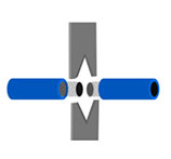 ESC-BX1 Wire Cutting and Stripping Machine ESC-BX4 Wire Cutting And Stripping Machine ESC-BX30 Automatic Large Cable Cutting and Stripping Machine ESC-BX30S Sheathed Cable Automatic Cutting and Stripping Machine ESC-BXR Automatic Rotary Cable Stripping Machine ESC-BX6 Wire Cutting And Stripping Machine ESC-BX7 Wire Cutting And Stripping Machine ESC-BX8S Sheath Cable Cutting and Stripping Machine ESC-BX8PR Wire Cutting And Stripping Machine ESC-BX9 Automatic Cut and Strip Machine ESC-BX30SC Automatic Cable Wire Cutting and Stripping Machine ESC-BX120 Automatic Cutting and Stripping Machine ESC-BX30RS Multi-function Rotary Cable Stripping Machine ESC-BX120S Multi-core Cable Cutting and Stripping Machine ESC-BX60 Automatic Cable Cutting and Stripping Machine CS-9685 Coaxial Cable Cutting and Stripping Machine CS-9680 Automatic Coaxial Cable Stripping Machine ESC-BX300 Automatic Cable Wire Cutting And Stripping Machine ESC-BX16 Wire Cutting Stripping Machine ESC-BX20SF Flat Twin Wire Cutting and Stripping Machine
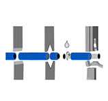 ACC-101 Automatic Single-head Terminal Crimping Machine ACC-102A Fully Automatic Terminal Crimping Machine (Both Ends) ACC-102B Automatic Double Terminal Crimping Machine ACC-105 Fully Automatic Single-head End-dipping Tin Machine ACC-106 Fully Automatic 5-Wire Single-head End-dipping Tin Machine ACC-202UP Fully-automatic cut,strip,crimp,insert and Heat Heat-shrink tube machine ACC-308 (Both ends) Full automatic Soldering machine ACC-208 Fully Automatic Crimping Machine (Both Ends) ACC-508 Fully Automatic Twisting, Soldering and Crimping Machine ACC-608 Fully Automatic Flat Cable Cut Strip and Crimp Machine
 HSM-60 Heat Shrink Tube Processing Machine HSM-70 Heat Shrink Tube Processing Machine HSM-80B Heat Shrink Tube Processing Machine HSM-90 Heat Shrink Tube Processing Machine HSM-25M Heat Shrink Tube Processing Machine HSM-120 Heat Shrink Tube Heating Machine HSM-50 Heat Shrink Tube Processing Machine HSM-160 Heat Shrink Tube Processing Machine HSM-80A Heat Shrink Tube Heating Machine HSM-260E Enclosed Heat Shrink Tube Processing Machine HSM-260O Open Heat Shrink Tube Processing Machine HSM-20 Intelligent Heat Shrink Tube Processing Machine
 HV-CS 9070 High-Voltage Cable Shield Cutting Machine HV-FS 9053 Cable Shield Folding Machine HV-ACS 9100 Cable Shield Processing Machine HV-ACS 9200 Automatic Cable Shield Processing System HV-ACS 9300 Automotive High Voltage Cable Processing Machine HV-ACS 9500 High Voltage Cable Processing Machine HV-FC 9312 Aluminum Foil Cutting Machine HV-CS 9120 Cable Stripping Machine
 STB-10 Automatic Tape Bundling Machine STB-50 Desktop Bundling Machine STB-60 Adhesive Tape Bundling Machine STB-55 Desktop Tape Bundling Machine STB-50C Automatic Tape Cutting Machine STP-B Hand-held Taping Machine STP-F Hand-held Lithium Battery Tape Wrapping Machine STP-C Automatic Wire Taping Machine STP-D Automatic Tape Wrapping Machine STP-AS Automatic Tape bundling Machine
 CB-B15 Automatic Wiring Winding Machine CB-BT15 Automatic Wiring Winding Binding Machine CB-F30/150MCS Automatic Wiring Winding Machine CB-F30/150MCST18-45 Automatic Wiring Winding Binding Machine CB-F30/150MCST40-80 Automatic Wiring Winding Binding Machine CB-B15CST Automatic Wiring Coiling Binding Machine CB-F500MCS Automatic Wiring Winding Machine CB-B30/150CS Automatic Wiring Winding Machine CB-B10/15CS Automatic Wiring Winding Machine CB-WT630 Automatic Wire Winding and Tying Machine
 PF-820 Wire Prefeeding Machine PF-08 Automatic Wire Prefeeder PF-30 Automatic Prefeeding Machine PF-60 Automatic Prefeeding Machine PF-150 Automatic Wire Prefeeding Machine CC-380 Cable Coiling Machine CC-680 Automatic Cable Coiling Machine CC-380D Cable Coil Machine PF-120 Large Automatic Wire Prefeeding Machine PF-90 Automatic Wire Prefeeder PF-100 Automatic Prefeeder PF-04 Automatic Wire Prefeeder PF-06 Automatic Wire Prefeeder PF-05 Automatic Wire Prefeeder
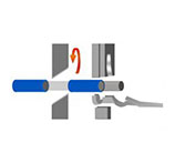

 CHM-10 Crimp-Height Measurer PFM-220 Terminal Pulling Force Tester PFM-300 Terminal Pulling Force Tester PFM-200 Pull Force Tester For Wire Terminals TCA-120 Terminal Cross Section Analyzer TCA-120S Terminal Cross Section Analyzer TCA-150 Terminal Cross Section Analyzer PFM-50 Pull Force Measuring Machine